Middlebury Formula Hybrid
I founded MFH in February 2021 to bring engineering to a liberal arts school; I’ve always had a passion for working on cars and thought other students might too. Between our club’s founding and our first competition in May 2022, a team of about 15 students worked to bring a complete car to the Formula Hybrid competition at the New Hampshire Motor Speedway. We began building in the Fall of 2021 thanks to Dartmouth, who sold us parts left over from their 2018-2020 car. Below are some of the projects I helped work on.
PCB Design
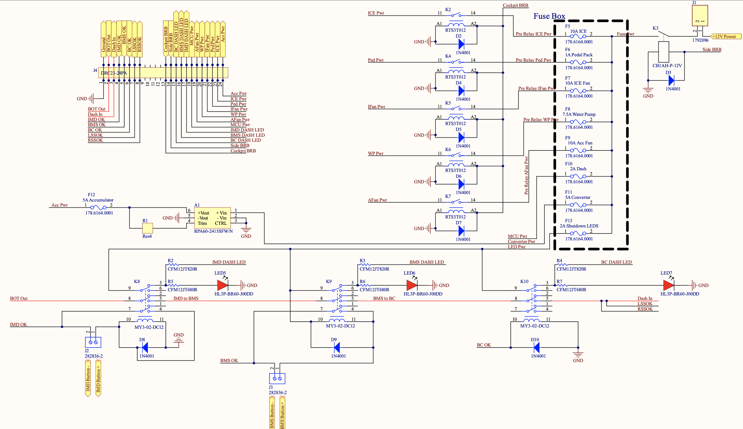
I designed the low voltage PCB for the car in Altium, which acted as a fuse box, distributed power to the pumps, fans, dash lights, ICE, and accumulator, and shut down the car based on error signals sent from the accumulator. The wiring and black duct tape in the last photo is a jury-rigged latching relay I put together at competition to make the car rules compliant.
Brake Over Travel Switch
Formula Hybrid requires a switch that shuts off the car in the case of a brake failure. I designed this adjustable switch mount in Solidworks and sent it to Mechanical Advantage, a local CNC shop, to be machined. Because the smaller plate has threaded holes, it can move forward and backward by turning the two mounting screws to achieve the correct distance where the switch is not depressed too early or late. The switch position can also be adjusted within the second plate so that the plate acts as a mechanical stop after the switch has been depressed.
Nosecone (with Rohan, Alex, Will, and Dane)
I created a template of the nosecone in Solidworks which the teammates used make a male mold, which was overlayed in fiberglass, carbon fiber, and epoxy.
Drivetrain Mount (with Dane)
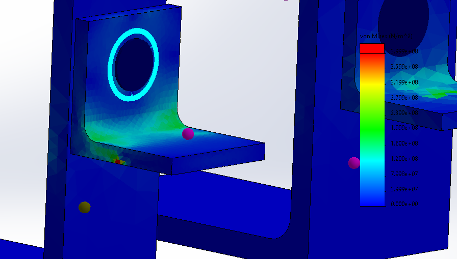
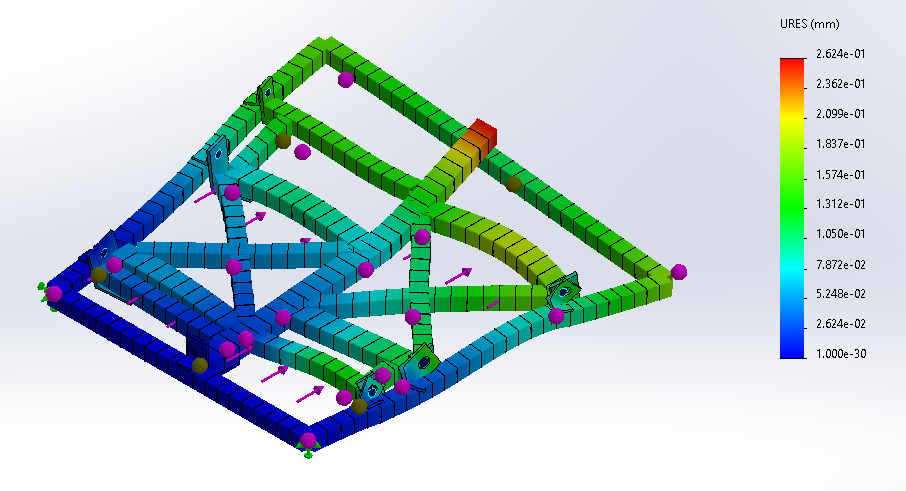
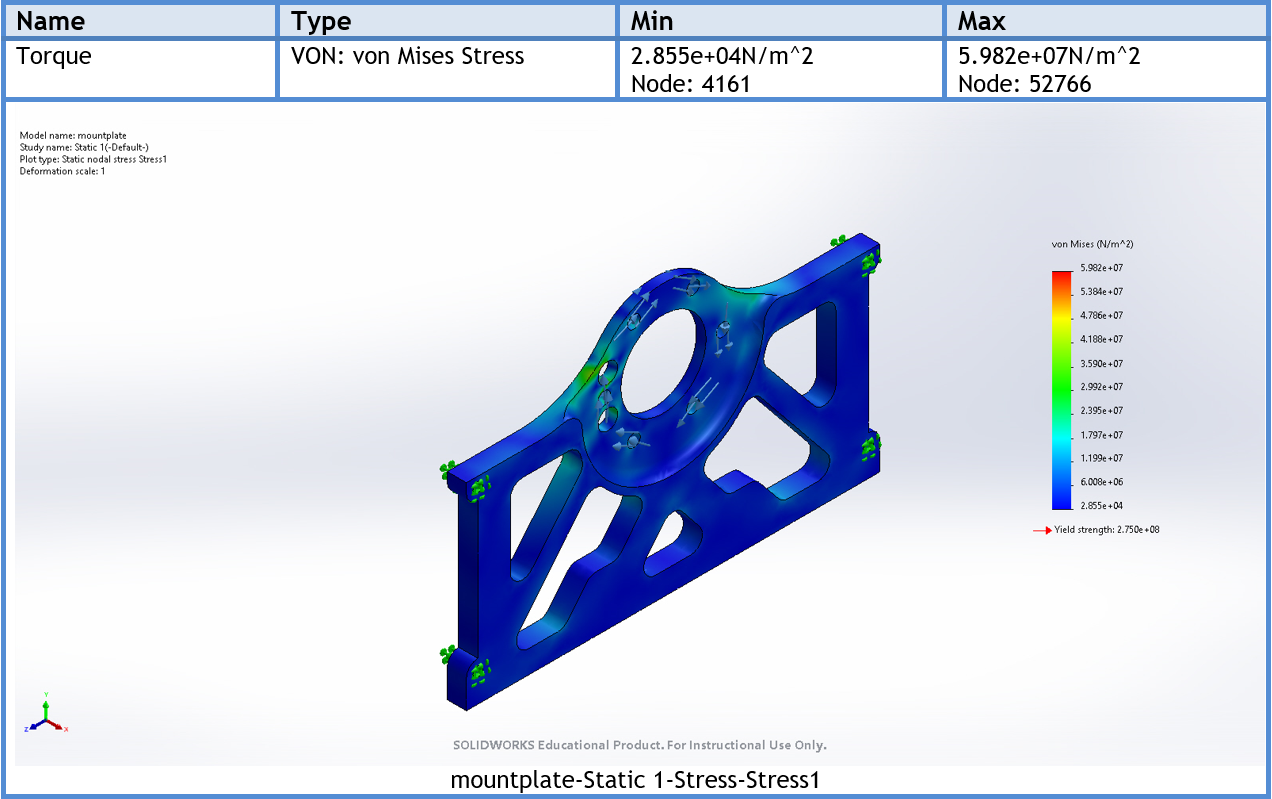
The drivetrain mount attaches to the chassis and the drivetrain components. Dane and I used Solidworks FEA to simulate a 40G deceleration on the mount to confirm that the brackets would be strong enough to hold the drivetrain components in the event of a crash.
Wiring Harness
The wiring harness connects the KTM engine, accumulator, lights, sensors, LV battery, and switches. It was also designed to incorporate CAN Bus for the throttle position sensor on the KTM to send messages to an Arduino which would send torque commands to the Bamocar motor controller in the accumulator. However, the CAN Bus system was not fully operational by competition due to some pending questions I had about arc flashes with the 300V battery, so I decided to play it safe and run the car combustion-only for year one.
Other (Dashboard, Improved Version of Dartmouth’s EMRAX mount, CAN Bus Tests)
Some of the other small projects I worked on. The dashboard included a shutdown button, Ready-to-Drive buzzer, warning lights, and ICE starter button. Rohan and I slightly reinforced Dartmouth’s EMRAX mount design which was CNC’d at Mechanical Advantage. The last photo is an early successful test of the CAN system which sent information from a POT sensor to a display.
The End Result
The competition was a great experience. We passed mechanical inspection, electrical inspection, and a noise and rollover test. Unfortunately, at the start line of the brake test, we had an electrical short that burned up a section of the wiring harness and took us out of competition for the day.


